Non-Manifold Edges in STL Files
Can STLFixer fix this?
- Try it for a small local defect: STLFixer can remove a single extra open triangle from an otherwise closed mesh when the checks support that edit. The example below shows exactly that case.
- Keep the original when the intended shape is unclear. General reconstruction, arbitrary internal faces and ambiguous junctions need a mesh editor. Preserve openings that belong to the design.
- Start with Upload STL. Inspect the diagnosis, review the small-hole option and select Repair STL. Compare Before and After, then check the saved file's dimensions and layers in your slicer.
Example: one extra open triangle
This synthetic teaching file is a closed tetrahedron with one extra open triangle attached along an edge. In the verified browser run, Repair STL reduced 5 triangles to 4, non-manifold edges from 1 to 0 and open edges from 2 to 0. The same four core faces and their coordinates remain; the bounding box stays 10 × 10 × 10 STL units.
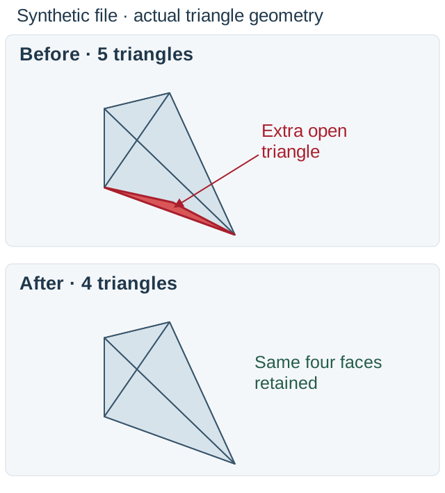
Geometry visualization computed from the two actual files, using the same view and scale. The transparent core makes the extra triangle visible; this is a diagram of the file geometry.
Download the input STL · Download the repaired STL · Reproduce the example and check its file hashes.
To repeat the run, upload the input, leave the default small-hole option enabled for this example and select Repair STL. Compare the Before and After views before downloading. This one constructed example does not establish which parts of your own model are surplus. General reconstruction and arbitrary internal-face removal remain unsupported; check units, intended openings and slice layers before printing.
What the slicer reports
Read the label beside a warning before interpreting its number. An edge count, a vertex count, and a count of affected faces describe different things. The diagnosis at stlfixer.io separates non-manifold edges from vertices and reports open boundaries separately.
Why the number differs between slicers
Bambu Studio's official message templates contain separate integer slots for non-manifold edges, vertices, and open edges.
Blender's Non Manifold selector includes boundaries, wire edges, multiple-face connections, and orientation conflicts.
Those categories cannot be compared as interchangeable totals. Compare the same file and processing stage, with the same category enabled. Preserve each diagnostic's wording and software context instead of treating a larger total as evidence of worse damage.
A difference can also reflect connectivity: CGAL's polygon-soup orientation uses shared point indices, so equal positions alone do not make faces adjacent. Point-merging policy matters when comparing categories.
What "3 non-manifold edges" actually means
As a teaching example, suppose your diagnostic says 3 non-manifold edges. In a count-based message, that means edges were counted; it does not identify an error code or tell you how much surface must change. This is a hypothetical reading, not a reproduced diagnosis.
How to confirm it's a real defect
Are non-manifold edges bad for 3D printing? They can obstruct a usable slice, but the warning alone does not establish failure. In a Cura 4.5 issue, missing layers were linked to non-manifold geometry; a contributor recommended Keep Disconnected Faces, which the reporter confirmed resolved the problem.
That setting artificially closes open contours with straight lines, so a completed slice still needs inspection for invented material. An OrcaSlicer 2.1.1 collaborator reported that the particular calibration models in a warning report could slice and print. These are different cases, not a guarantee for every junction. Check the affected layers for missing walls, sealed passages, or unwanted joins before accepting the result.
Manifold vs. non-manifold
In the topology-graph paper, a boundary edge touches a single face, a non-manifold edge touches more than two, and a turning edge joins inconsistently oriented faces. The product counts open boundaries separately from overloaded edges. A boundary opening and an overloaded junction therefore need different diagnoses.
Self-intersections need a separate check: CGAL's combinatorial manifold definition does not exclude them or degenerate geometry. Inspect the exact layer where the suspicious junction enters the material outline, and compare its neighboring layers. A clean connection count cannot clear a crossing surface. The product can report intersections without locations; an absent highlight does not prove absence.
What causes it
Start with the connection that was detected, rather than blaming the export command. The local analysis gives identical coordinate positions shared vertex identities, then counts how faces use each edge. That means the diagnosis concerns the relationships represented in the imported mesh, not an explanation of which earlier editing action created them.
Coincident geometry and connectivity also need separate attention. CGAL's polygon-soup orientation procedure defines adjacency through shared point indices; merely equal positions do not establish that relationship until matching points are merged.
This supplies a reason to record the diagnostic definition and point-merging policy before comparing results. It does not establish why a particular pair of slicers disagreed on a particular file.
There is a documented modeling limit worth checking: Blender's Simple Solidify mode cannot handle an edge shared by more than two faces, and inconsistent neighboring directions can prevent it from closing a boundary.
That describes a tool's input limitation; it does not prove Solidify created a new non-manifold edge in an initially valid object. In a Cura 3.4.1 issue, a contributor instead traced missing head contours to a nose attached using loose polygons rather than a closed volume.
Keep the modeling file and exported mesh together when investigating. Without a before-and-after comparison, describe the observed connection and the operation sequence, not an unverified exporter defect.
When you should leave it alone
Leave the original file unchanged when the proposed correction would seal an opening you intend to keep. The small-hole option can add surface triangles and is initially selected when an open boundary is diagnosed. Clear it before requesting repair if that opening belongs to the design. This expresses your choice; it does not turn an open mesh into a verified downloadable result.
With hole closing disabled, a remaining open boundary stops output and the viewer retains the input. The current release does not export that open mesh as a repaired file. Keeping the original is therefore a meaningful outcome even when no replacement download is offered. Do not enable sealing merely to make a download available.
Some local non-manifold defects can now be handled, including a single extra open triangle attached to an otherwise closed mesh when the checks support that edit. This is a bounded repair path, not general reconstruction. Other connections remain unsupported, and a lower warning count does not prove the intended shape was preserved.
Location information has limits. Red edges and points are available only when the location analysis agrees with the core count. If they disagree, the layer is disabled. Do not choose faces for deletion from a location display that the tool has explicitly withheld. The original remains available for inspection after refusal.
The output checks require closed, consistent, intersection-free geometry, but they do not establish your intended openings or validate wall thickness. A clean diagnostic therefore cannot replace a design decision about which spaces must remain empty.
If the slice already represents your intended material, preserve that file and its settings as a comparison. Make any junction edit on a copy, and reject the edit if it seals a passage or joins separate parts.
How to fix it
Keep an untouched copy and identify what each suspicious connection should represent before editing. The goal is an interpretable material boundary, not a smaller warning total.
- In Blender, enter Edit Mode, choose Vertex or Edge selection, and use
Select > Select All by Trait > Non Manifold. - Adjust the selector's options to distinguish boundaries from edges shared by multiple faces and from direction conflicts.
- For a confirmed opening you intend to close,
Mesh > Clean Up > Fill Holesfills selected holes, with a limit on their side count. - For confirmed surplus faces,
Mesh > Delete > Only Facesremoves selected faces while leaving orphaned edges and vertices; inspect the remaining surface afterward.
Do not delete everything selected by the diagnostic. A boundary, a conflicting direction, and an overloaded connection require different decisions. Record the intended surfaces on each side of the junction before selecting anything for removal. If you cannot determine which surface should exist at the junction, return to the modeling source instead of guessing from the warning.
You can inspect the file with this browser-based STL repair tool before attempting changes. It accepts a single nonempty STL up to 50 MB, with a basic processing limit of 1,000,000 faces; special local intersection processing has a separate 100,000-face limit.
The tool inspects the input before attempting repair. A supported local non-manifold defect may be repaired automatically, but arbitrary internal faces, ambiguous junctions and general reconstruction remain unsupported. The output must pass the remaining checks before download. Keep the original and inspect the changed area in your slicer.
How to verify the fix
Compare the result with the original at the connection you intended to change. Check the surrounding surface as well: a lower warning count does not establish that the correct faces survived. Keep the original available until you have inspected the repaired geometry and the intended empty spaces.
The final exported bytes are parsed and diagnosed again. Download eligibility requires closed manifold geometry, consistent winding, finite coordinates, and no remaining intersections, duplicate faces, degenerates, or non-manifold connections. A completed cleanup stage alone is insufficient.
Read unavailable information literally. If the location layer is disabled, use the reported count without inventing an exact position; if intersections are reported without highlights, continue investigating them.
Reimport the saved result into your intended slicing workflow and inspect the layer paths around the edited area. Confirm that intended passages remain open and intended material remains present. Review the paths before printing, especially where repaired surfaces meet intended passages. The geometry result does not validate wall thickness or guarantee a successful print.
Start with the original STL and a clear description of the connection you want to preserve. Inspect the diagnosis before requesting changes, and keep the original if a proposed operation would alter an intentional opening. A downloadable result still needs your review of the design and the resulting slice.
Repair an STL file